35+ water level indicator block diagram
The working of the complete water level indicator project is shown in below block diagram. In industry the water level control problem is a typical process control problem and has been extensively studied in the literature.

Water Level Indicator Circuit Gadgetronicx Electronics Design Electronic Schematics Diy Electronics
LED WATER LEVEL INDICATOR WITH ALARM Aditya Sharma.

. Kh2 data battles recommended level. Water Level Indicator Circuit Schematic CD4511 datasheet 74147 datasheet Assemble the water level indicator circuit on a general-purpose PCB and enclose in a box. The circuit diagram of the water level controller is shown in the figure below.
The circuit is based on an astable multivibrator wired around ic1 ne 555the operating frequency of the astable multivibrator here will depend on capacitor c1 resistances r1r2 and the. This report focuses on the design and. Its free to sign up and bid on jobs.
Its free to sign up and bid on jobs. We can see how the LEDs light up sequentially in. The pin out diagram of the IC Simulation.
Block Diagram For Control Systems. One output GPIO pin is directly connected to the. Search for jobs related to Block diagram of water level indicator or hire on the worlds largest freelancing marketplace with 19m jobs.
This circuit not only indicates the amount of water present in the overhead tank but also gives an alarm when the tank is full. A rough simulation of the discussed water level indicator circuit is shown below. The above image shows the internal block diagram of the IC LM35.
Components Required for Water Level Alarm Circuit 4 - BC547 transistors 6 - 220 ohm resistors 3 - Colour LEDs - red green and yellow 1 Buzzer 5 - 9v battery battery clip. Block Diagram For Water Level Indicator Read Block Diagram For Water Level Indicator PDF on our digital library. Similar to automatic water level controlling.
Free standard shipping for orders petition for change of name washington. You can read Block Diagram For Water Level Indicator PDF direct on your. Reims vs angers sporticos.
It process the data given by the Receiver Section. The sensing is done with a series of. Circuit Diagram Water Level Indicator Controller using PIC Microcontroller The soul of the Controlling Section is PIC16F877A.
When the water is empty the wires in the tank are. Heres a simple water level indicator for overhead tanks that uses three LEDs LED1 LED2 and LED3 to indicate minimum middle and maximum water levels in the tank. Electronic set up of the Water Level measuring system.
Block diagram of water level indicator using transistorused cars memphis under 8000. The Water Level Indicator detects and indicates the water level in an overhead tank or some other water container using a simple mechanism. Search for jobs related to Water level indicator project block diagram or hire on the worlds largest freelancing marketplace with 21m jobs.
What does congressional gridlock mean. Here we can see that the IC is internally configured around a couple of opamps A1 and A2. Block Diagram of Arduino based Wireless Water Level Indicator Circuit Connections The Project has two circuit sections.
Genre and subgenre worksheet 2 answer key. The first opamp A1. Block Diagram Of Water Level Indicator - Read Block Diagram Of Water Level Indicator PDF on your Android iPhone iPad or PC directly the following PDF file is submitted.
One is the water level detection circuit and other is the motor. The ESP 32 is powered with 5 V from the USB port and has a 3 3V regulator on board.
2
Where Is The Power Button On A Rog Strix Z390 E Gaming Motherboard Quora
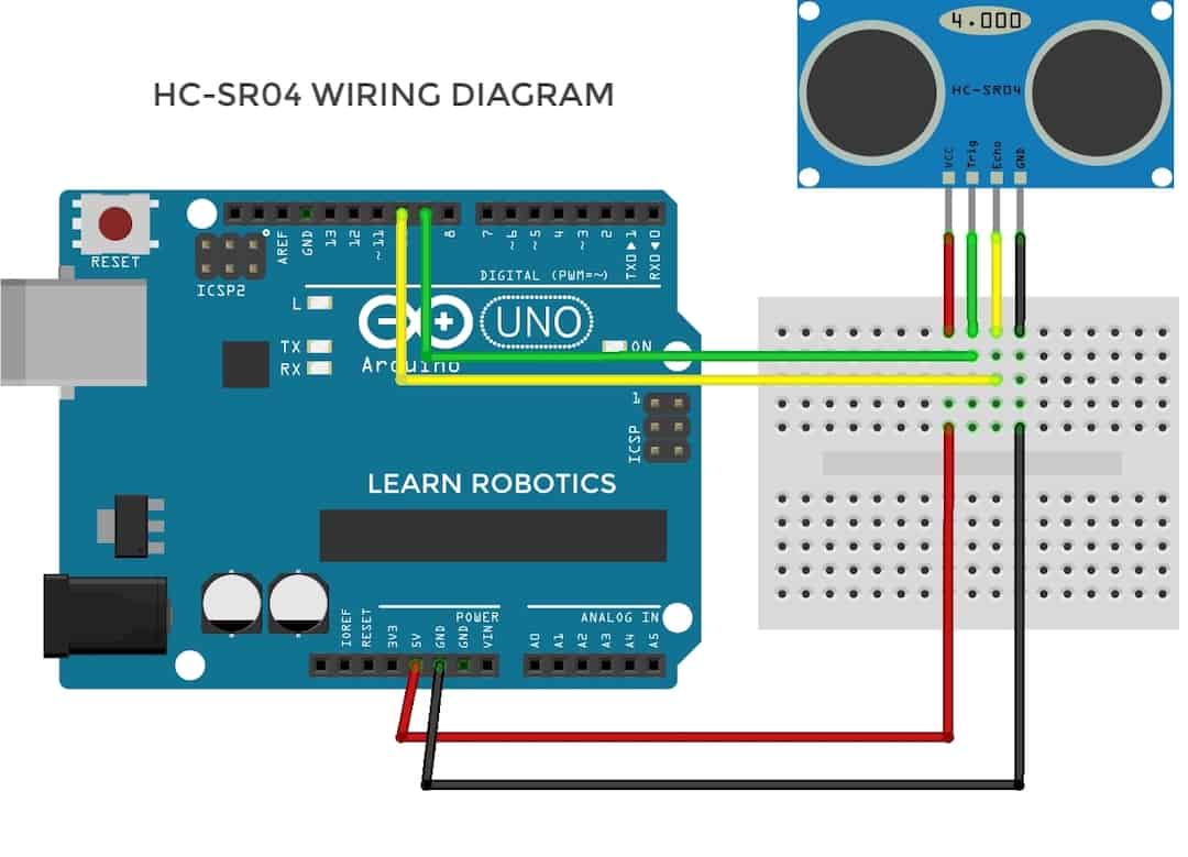
Ir Sensor Vs Ultrasonic Sensor What Is The Difference Learn Robotics

Water Level Indicator Using 7 Segment Led Circuit Electronique Electronique Pratique Electronique Numerique
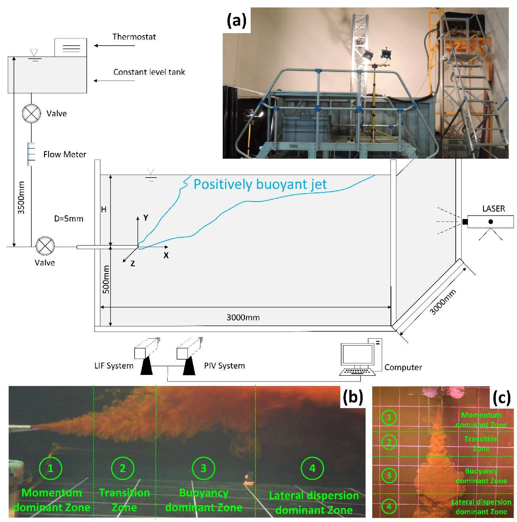
Water Free Full Text Zonation Of Positively Buoyant Jets Interacting With The Water Free Surface Quantified By Physical And Numerical Modelling Html

Water Level Indicator Project Circuit Working Using Avr Electrical Projects Electronics Mini Projects Circuit Diagram

Water Free Full Text Use Of Wrf Hydro Over The Northeast Of The Us To Estimate Water Budget Tendencies In Small Watersheds Html

Drip Public Analytics Includes Average Borehole Runtime Per Download Scientific Diagram

Water Level Sensor Circuit Schematic Rangkaian Elektronik Elektronik Aplikasi

Numeric Water Level Indicator Liquid Level Sensor Circuit Diagram With 7 Segment Display Engineering Proj Circuit Diagram Level Sensor Electronic Schematics

Numeric Water Level Indicator Liquid Level Sensor Circuit Diagram With 7 Segment Display Engineering Project Circuit Diagram Level Sensor Circuit

Water Level Indicator Alarm Circuit Electronics Circuit Circuit Diagram Circuit Board Design
Quattroworld Com Forums C4 Starting Circuit Wiring Diagram

Water Free Full Text Zonation Of Positively Buoyant Jets Interacting With The Water Free Surface Quantified By Physical And Numerical Modelling Html
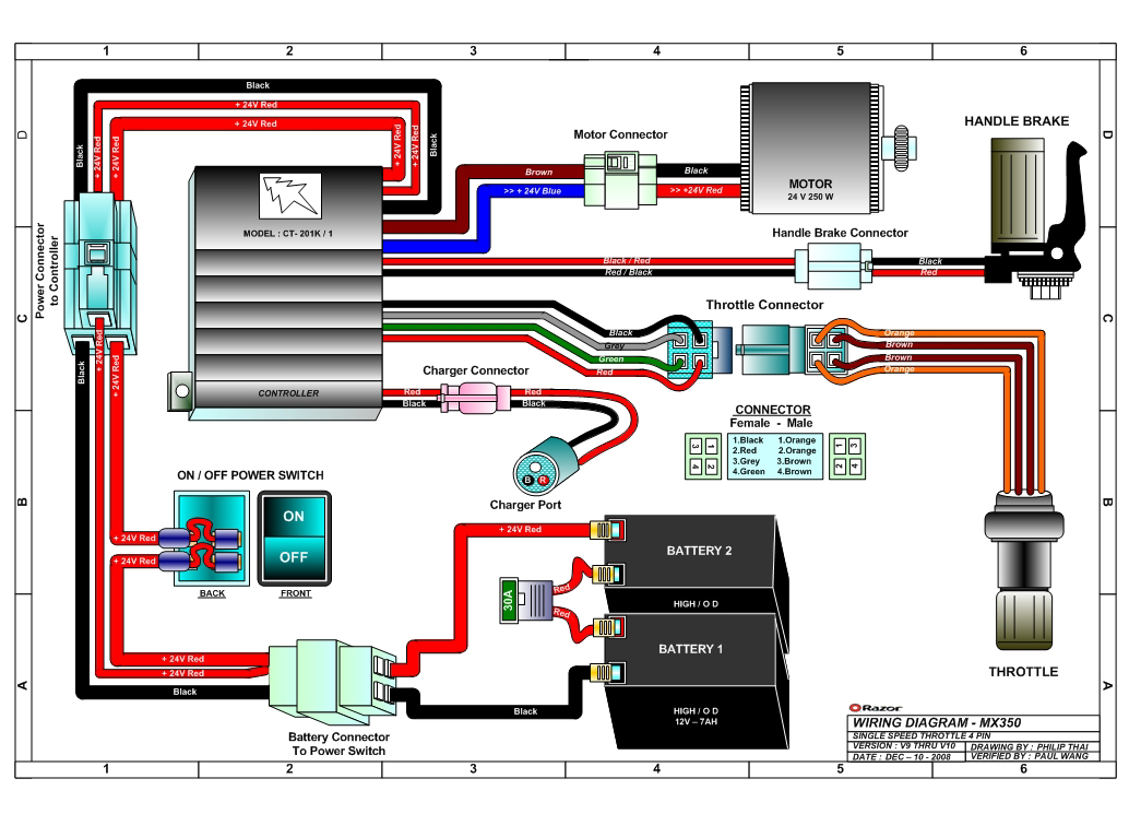
Razor Zr350 Electric Dirt Bike Parts Electricscooterparts Com

Project 003 Arduino Lm35 Temperature Sensor Project Arduino Project Hub

Water Free Full Text Use Of Wrf Hydro Over The Northeast Of The Us To Estimate Water Budget Tendencies In Small Watersheds Html